Topic Content:
- Step-by-Step Orthographic Projection
- Worked Illustration
- first angle orthographic projection
- third angle orthographic projection
- Worked Illustration
Illustration:
Draw the Isometric drawing object shown below, with the given dimensions, in first & third angle orthographic projection. The dimensions are in mm (1cm = 10mm).
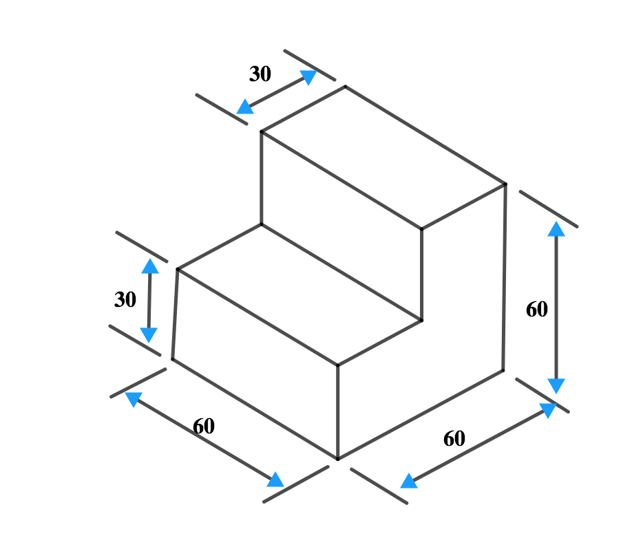
First Angle Projection:
Steps:
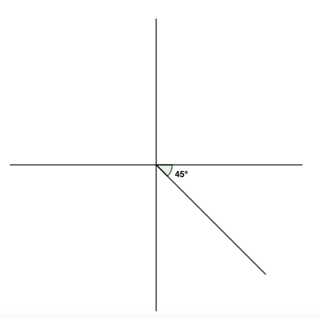
a. Draw both the vertical and the horizontal axis to intersect midway.

b. Draw a 45° projection line from the intersection as shown below.
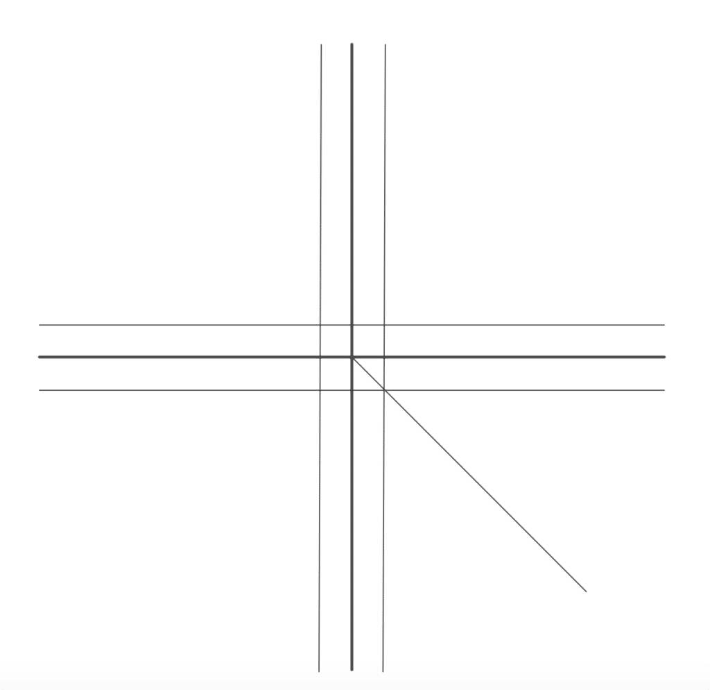
c. Next step is to put spaces in both the horizontal and vertical axis.
Add a 10 mm space to the left and a 10 mm space to the right side of the vertical line. Then draw lines parallel to the vertical line
Add a 10 mm space to the top and 10mm space to the bottom of the horizontal line. Then draw parallel lines to the horizontal line.
Make sure that the lines are very faint.
This is shown below.
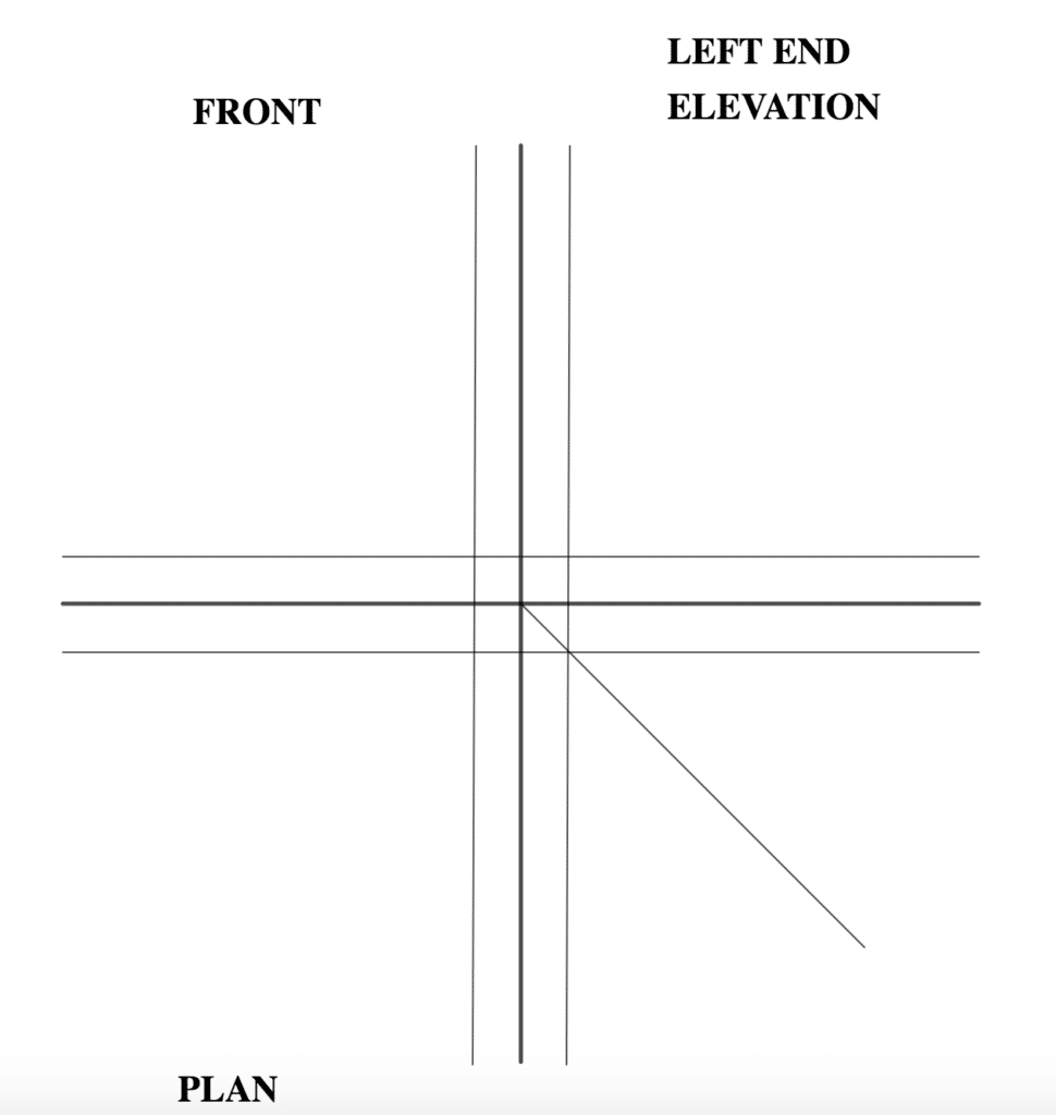
d. Determine the placement of the views and label the diagram accordingly.
This is a first angle projection so It should be noted that the left side elevation is usually placed at the right-hand side and the right-hand side is placed at the left-hand side.
In the diagram we can see that the side view is on the left, so we will label it on the right of the front view.
The plan is located below the front view in first angle projection.
e. Front View: First you measure 60mm up and 60mm to the left. From the diagram, the other sides are 30mm. So from the top, we will draw 30mm to the left, 30mm down, 30mm to the left again and finally 30mm to complete the front view.
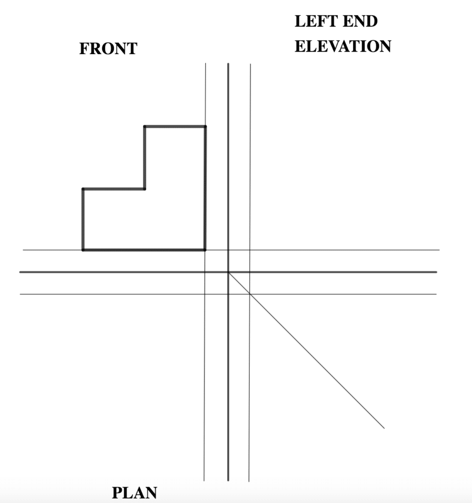
f. Add dimensions to the front view.
You are viewing an excerpt of this Topic. Subscribe Now to get Full Access to ALL this Subject's Topics and Quizzes for this Term!
Click on the button "Subscribe Now" below for Full Access!
Subscribe Now
Note: If you have Already Subscribed and you are seeing this message, it means you are logged out. Please Log In using the Login Button Below to Carry on Studying!


Drawing this was very hectic but rewarding, I’ve learnt a lot in a matter of minutes.
Thanks to the Kofastudy team ❤️😊